Tutorial ABAQUS: A Comprehensive Guide for FEA Beginner
- Daniel M.Saylor
- Mar 31, 2023
- 5 min read
Updated: Feb 2, 2024
ABAQUS is a robust, industry-leading software tool used for finite element analysis (FEA) across various engineering disciplines. Engineers rely on ABAQUS to study the behaviour of structures and materials under diverse loading scenarios, making it an essential resource for product design and research. This tutorial offers a thorough introduction to ABAQUS, exploring its applications, components, and a brief overview of the software's user interface.
Table of Contents:
Understanding ABAQUS
ABAQUS is a collection of software applications designed to conduct finite element analysis, a numerical method for addressing intricate engineering problems. Industries such as automotive, aerospace, civil engineering, and biomechanics frequently employ ABAQUS for simulating the performance of structures and materials under a range of conditions, including static, dynamic, and thermal loads.
ABAQUS Applications
ABAQUS can tackle numerous engineering challenges, including but not limited to:
Linear and non-linear static analyses
Dynamic and vibration analyses
Thermal analyses
Fluid-structure interactions
Composite materials analyses
Fracture and fatigue analyses
ABAQUS Components
ABAQUS comprises several components, each fulfilling a specific role in the FEA workflow:
ABAQUS/CAE (Complete ABAQUS Environment): The primary graphical user interface (GUI) for building, editing, and analyzing models.
ABAQUS/Standard: The core solver for linear and non-linear static and dynamic analyses.
ABAQUS/Explicit: A distinct solver tailored for highly non-linear, transient dynamic analyses involving extreme discontinuities or significant deformations.
ABAQUS/CFD: A dedicated component for conducting computational fluid dynamics simulations, often used in tandem with structural analyses for fluid-structure interaction problems.
Navigating the ABAQUS/CAE User Interface
The ABAQUS/CAE interface is organized into distinct modules, each concentrating on a particular stage of the FEA process:
Start: Create a new model, open an existing one or access recent models.
Model: Build and modify parts, materials, and sections, and assemble different parts into a unified model.
Property: Define material properties, create section assignments, and apply loads and boundary conditions.
Mesh: Generate and modify finite element meshes for your model.
Load: Apply loads, boundary conditions, and initial conditions to your model.
Step: Define analysis steps and output requests.
Interaction: Define contact interactions, constraints, and other interactions between model components.
Job: Create, submit, and monitor analysis jobs.
Visualization: View and analyze the results of your simulation.
How to Create a 3D Cantilever Beam Model in Abaqus: Example
Launch ABAQUS/CAE and start a new model in the 'Start' module.
In the 'Model' module, click 'Part' -> 'Create Part'. Name the part "Cantilever_Beam" and select '3D', 'Deformable', and 'Beam'. Click 'Continue'.
In the 'Sketcher' window, draw a straight line representing the length of the beam by clicking two points, and then click 'Done'. You can adjust the dimensions by entering the desired length in the 'Dimensions' box.
Next, we'll define the cross-section of the beam. Go to 'Section' -> 'Create Section'. Name it "Beam_Section" and choose 'Beam' as the category. Click 'Continue'. Select 'Rectangular' for the profile and enter the height and width of the cross-section. Click 'OK'.
Assign the section to the beam. In the 'Model Tree', click on 'Cantilever_Beam', then 'Section Assignments' -> 'Create'. Select the entire beam and choose "Beam_Section" from the list. Click 'Done'.
Now, create a new material for the beam. In the 'Property' module, click 'Material' -> 'Create Material'. Name it "Beam_Material". Define the material properties, such as density, Young's modulus, and Poisson's ratio, by clicking on 'Mechanical' -> 'Elasticity' -> 'Elastic'.
Assign the material to the beam section. In the 'Model Tree', click on 'Beam_Section' and then 'Edit'. In the 'Section Editor', click 'Material' and select "Beam_Material". Click 'OK'.
In the 'Assembly' module, click 'Instance' -> 'Create Instance'. Select the 'Cantilever_Beam' part and click 'OK'.
Move to the 'Step' module to create a new step for the analysis. Click 'Create Step' and name it "Load_Step". Select 'Static, General' as the procedure type and click 'Continue'.
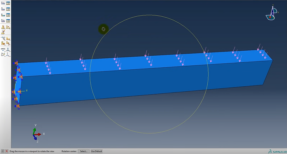
In the 'Load' module, apply a boundary condition to fix one end of the beam. Click 'Boundary Condition' -> 'Create Boundary Condition'. Name it "Fixed_Support", select "Load_Step" as the step, and choose 'Encastre' as the type. Select the end of the beam where you want to apply the boundary condition and click 'Done'.
Apply a concentrated load to the other end of the beam. Click 'Load' -> 'Create Load'. Name it "Point_Load", select "Load_Step" as the step, and choose 'Concentrated Force' as the type. Select the end of the beam where you want to apply the load, and enter the load magnitude in the 'Components' box. Click 'OK'.

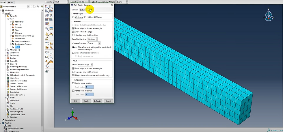
Proceed to the 'Mesh' module to mesh the beam. Click 'Seed Part Instance', choose the 'Cantilever_Beam' instance, and set the approximate global size for the mesh elements. Click 'OK'. Then, click 'Mesh Part Instance' and select the 'Cantilever_Beam' instance. Verify that the mesh is appropriate and adjust the seed size if necessary.

In the 'Job' module, create a new job for the analysis by clicking 'Job' -> 'Create Job'. Name the job "Cantilever_Beam_Analysis" and associate it with the current model. Click 'OK'.
Submit the job for analysis by selecting the job in the 'Job Manager' and clicking 'Submit'. Monitor the progress of the job and wait for it to complete.
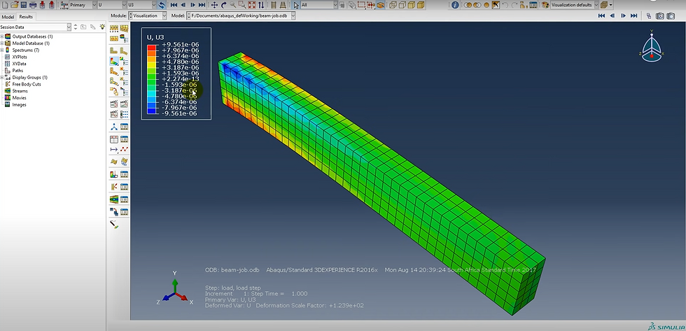
After the job has finished, go to the 'Visualization' module to view and analyze the results. Click 'Result' -> 'Field Output' to display the available field outputs. Choose 'Displacement' to view the displacements in the model.
To display the deformed shape of the beam, click 'Plot' -> 'Deformed Shape'. Adjust the display options as desired, such as adding contour plots or vectors to visualize the deformation more effectively.
Investigate the stress distribution in the beam by selecting 'Stress' from the available field outputs. Choose the stress component you are interested in (e.g., S11 for the axial stress) and display it as a contour plot or as values at the nodes.
To obtain specific numerical results, such as maximum stress or displacement, use the 'Query' tools. For example, click 'Query' -> 'Max/Min' to find the maximum and minimum values of the selected field output.
To plot a graph of a specific result along the length of the beam, use the 'XY Data' tools. Click 'XY Data' -> 'Create' and select the desired output (e.g., 'Stress'). Choose the appropriate options, such as averaging the data over the cross-section, and click 'OK'. Display the graph by clicking 'Plot' -> 'XY Data'.
Once you have analyzed the results and are satisfied with the model, save the ABAQUS/CAE session and the generated output files for future reference.

This tutorial provided a comprehensive introduction to ABAQUS, its applications, and its main components. You also gained a brief insight into the ABAQUS/CAE user interface. With this groundwork established, you are now prepared to delve into more advanced topics and begin creating and analyzing your FEA models using ABAQUS. You can also Contact Us to talk and get advice from our Experts.


Comments